Overview
When a substation is designed, there are many factors that need to be accounted for so that the substation will stand the test of time. Optimization of the bus arrangement for the initial layout and future expansion is, for most, the major design consideration. During the design phase, there are a considerable number of items to consider, with one of critical importance being Induced Vibration.
Induced Vibration that we regularly deal with in the design of a substation can be attributed to two forces acting upon the substation’s bus conductors: Wind and AC Current. By optimizing the bus design to account for induced vibration by adding cable dampeners inside the bus, there can be a significant reduction in the required maintenance due to reduced wear and tear of connectors, welds, insulators, and bolted connections, resulting in initial cost savings from sizing the conductors used in the substation to account for the induced vibration damping conductor.
Wind-Induced Vibration
The first and most recognizable force is wind. The IEEE 605-2008 standard breaks down the wind influence into two categories: below 45 mph and above 45 mph. The constant flow of wind below 45 mph around a conductor can induce a vibration at a specific frequency. When this frequency coincides with the natural frequency of the conductor, wind-induced vibration of the conductor occurs and can cause significant issues and damage. Wind gusts above 45 mph are usually too turbulent, and the probability is less likely that they will induce a consistent vibration in the conductor. However, they still need to be checked, as the conductor’s natural frequency could still fall within the calculated frequency range due to winds above 45 mph during vibration analysis.
AC Current-Induced Vibration
The second induced vibration can be attributed to the AC current flowing through parallel bus conductors. AC current induces magnetic fields that interact and cause an electromagnetic force on the parallel bus conductors. If this force occurs at the right frequency, it can induce vibrations within those parallel bus conductors. The AC current-induced vibration requires consideration if the conductor’s calculated frequency of the bus span is found to be greater than the power frequency, as noted in IEEE Standard 605-2008 formulas.
Both induced vibration forces, wind and AC current, need to be evaluated to ensure that they are accounted for because over time or if the vibration is consistent, they could cause damage to conductor fittings, insulators, or seam welds.
Mitigating Induced Vibration
IEEE Standard 605-2008 provides a solution to counter the induced vibration. It is called vibration attenuation or cable damping. This solution involves the installation of a cable inside the tubular bus, which reduces or dampens the induced vibration with a cable counterweight. This vibration control through cable damping is in addition to other design criteria, such as setting optimum span lengths and sizing the tubular bus diameter based on designed span lengths, all of which help with induced vibration control. Despite the need for cable damping, there are instances when damping isn’t needed. IEEE Standard 605-2008 provides minimum recommended spans without cable damping based on tubular bus diameter. Those minimum lengths are provided below in *IEEE Standard 605-2008’s Table 19.
Best Practices
At NEI, we have the standard practice of always placing damping cable inside the tubular bus, except for the A-Frame legs. This practice of always installing damping cable covers situations where there may not be a requirement for damping of the tubular bus, but it ensures we do not overlook installing the damping cable should the length of the tubular bus require damping if it is at or near the minimum length for cable damping. It also ensures that the conductor gets installed when it is required. The damping cable should be within the guidelines discussed in IEEE Std. 605-2008 – IEEE guide for Bus Design in Air Insulated Substations: Section 12.7 Vibration attenuation and should usually be chosen from a conductor type already in use at the site or sized to mitigate costs.
The range of weight that can be used as a damping cable allows for the use of conductor that is most likely already being used within the substation as main feeder cable or as jumpers. The following is a text link to a published list from Priority Wire for their All Aluminum Conductor (AAC) properties, used in the example below. Link to Priority Wire’s AAC properties
Table 1 —Unit weight and section modulus of aluminum bus
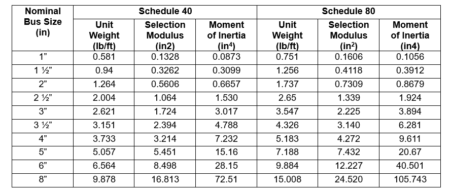
EXAMPLE: The tubular bus conductor has been determined to be 4”, Schedule 40, AL 6061-T6 based on ampacity requirements with multiple span lengths ranging from 15ft to 80ft. The first step is to determine the range of weight the damping cable can be, which is 10% to 33% weight of the 4” Bus which is 0.3733lbs to 1.232lbs based on the values from Table 1. Using the Priority AAC conductor table, the allowable weights for the damping cables (weights are listed in lbs per 1000ft, so remember to divide by 1000), we could use conductors between 397.5 AWG Canna at .3732lbs and 1272 kcmil Narcissus at 1.194lbs. Choosing cables from the table between those weights would allow for the more common jumper cable 477 AWG Cosmos, and feeder cables of 795 AWG Arbutus or even the 1000 kcmil Hawkweed. Hence why there is a range for the damping cable to accommodate for the cable already being used in the substation. As a reminder these damping cable weights would also have to be included in the maximum bus span calculations once chosen.
Conclusion
Vibration damping conductors should be applied when the maximum vibration-free span length exceeds the limits listed in Table 19 for tubular bus conductor types, as copied from *IEEE Std. 605-2008 – IEEE guide for Bus Design in Air Insulated Substations, Section 12.7 Vibration attenuation.
*Table 19 —Maximum vibration-free span length for tubular bus
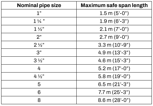
NOTE: These lengths are based on one cycle of vibration and apply to both the schedule 40 and the schedule 80 tubular bus. The lengths listed here can be increased approximately 20% with reasonable certainty that there will be no vibration.
Contact Our Team
Ready to ensure the longevity and reliability of your substation? Reach out to our team of engineering experts today. Let’s work together to optimize your substation’s performance.